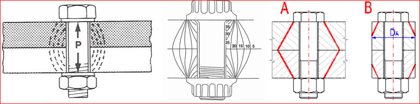
Engineers occasionally run across situations where bolted joints have “loosened” even when head and/or nut positions have been marked with scratches or paint. This is known as “non-rotational loosening”. Several things can cause that. First of all, the components within the grip of the fastener must be checked for yielding (embedment or creep), causing “joint relaxation”. Various authors represent the clamping effect of the bolt upon the joint as a barrel-shaped stress pattern or a diamond-shaped pattern (see below). The angle of the diamond varies between 30° and 45°, depending on the author. The International Fastener Institute says for a rigid joint of reasonable thickness, a compression area of three times the bolt area is conservative. These are useful in determining the stiffness of the joint components, but that is a subject for another discussion. The one thing they all agree on is that the maximum compressive stress occurs directly under the head of the bolt or nut.
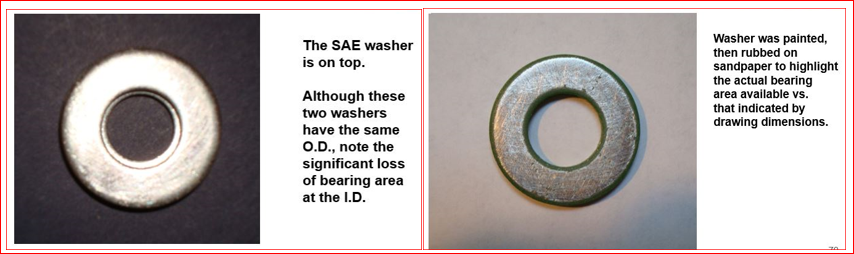
Bearing area plays a big part in this apparent loosening of the joint. Begin by calculating the minimum possible interface between the underside of the bolt head and the clamped part. Look at the parts and measure them to determine the true bearing areas. DO NOT ASSUME that diameters specified or shown graphically accurately represent the actual areas. For example, the underhead bearing O.D. of hex head capscrews and nuts is specified to be equal to the distance across-flats. In actual practice the washer face O.D. may be up to 15% smaller by ANSI/ASME B18.2.1 standards, which has a significant effect on bearing area. Using a 3/8-16 hex head capscrew as an example, the distance across-flats is 0.5625” maximum, less 10% for the minimum = 0.5025”. The capscrew has an underhead fillet diameter of 0.425” maximum allowable and 0.405” minimum. In the max/min condition, the bearing area is 0.1197 in2 and in the min/max condition, the area is only 0.0565 in2, less than half the maximum bearing area. If the fastener is applied directly against the clamped part, the maximum hole size should be used in calculations. Holes in washers, parts and nuts commonly have a chamfer or rounded edge which further increases the maximum I.D. used for bearing area calculation. If unknown, assume that a machined hole lead-in is 1 x pitch; for the 3/8-16 bolt, 1 x 1/16 = 0.0625”, (= 0.031” x 45°chamfer). Similarly, each interface between components in the joint must be checked for yielding. If high levels of stress are encountered, either the torque spec must be reduced, bearing area must be increased to distribute the stress, higher strength materials must be used or hardened washers must be added to the joint to reduce bearing stress to acceptable levels.
Note on washers used within a joint: DO NOT use a standard SAE washer in any joint you want to keep tight! There are three reasons for this statement:
First the material specified is very soft and will yield under even light preload. The material specs are: “the washers shall be punched from hot-rolled, hot-rolled and pickled or cold-rolled steel; or shall be machined from bar stock or tubing”. Also, “Unless otherwise specified, the washers are not furnished to mechanical requirements, and the hardness may vary in any production lot.” As you can see the only restriction is that these washers must be made from steel, which could be as soft as 24 ksi minimum yield. Always design for “worst-case” conditions, because your designs will encounter them at some point in their life cycle.
Second, the I.D. of SAE washers is excessively large, ensuring that you end up with insufficient bearing area to support your desired preload.
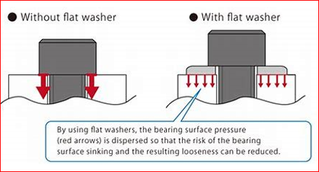
Third, they are not hardened, so that under load they just “dish” upward without providing the bearing surface their dimensions would suggest. Hex head capscrews will experience major embedment into these soft washers and no amount of re-tightening the screws will maintain the preload. The use of flanged or large-headed fasteners and/or hardened washers is recommended instead.
Another cause of non-rotational loosening is embedment or relaxation of the material under the bolt head. Fasteners used in joints involving softer metals, such as aluminum, brass, copper, magnesium or Zamak die casting alloys, frequently experience joint relaxation. This underhead metal creep or deformation occurs when the preload is excessive for the design’s bearing area. It is not unusual with these softer materials to see 10% to 15% loss of preload after some time interval. Re-torquing the joint will not solve this problem. The only way to do so is to increase the bearing area, thereby decreasing the compressive stress.
The plot below shows a time lapse measurement of initial clamp load deterioration. The Grade 8 fasteners were checked periodically by ultrasound for relaxation of the 390 die-cast aluminum joint material.
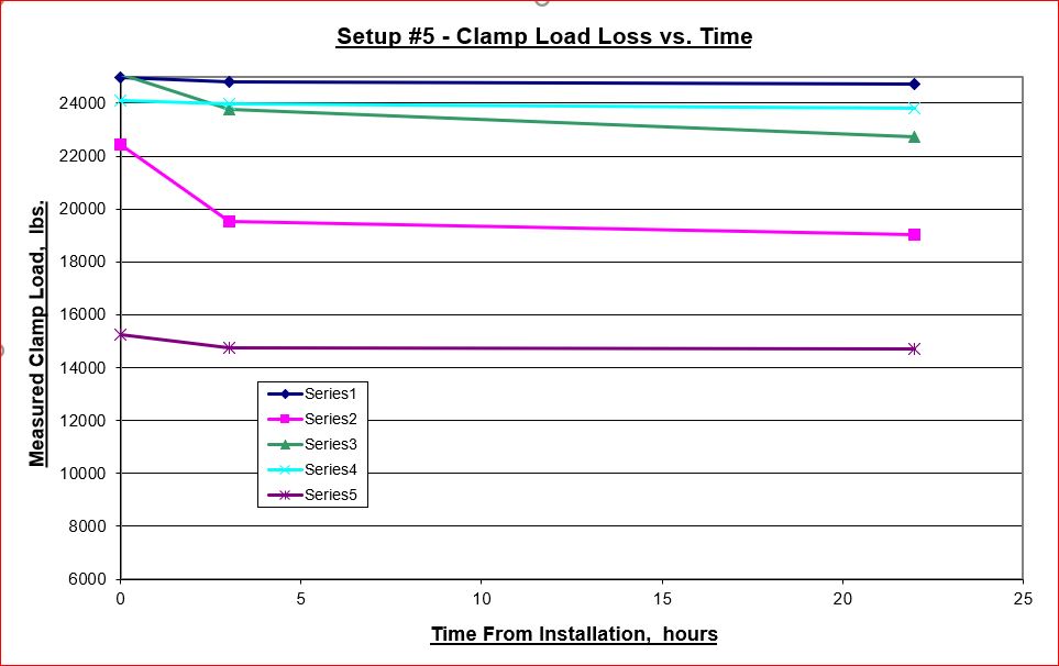
As the plot of these five screws show, the majority of the preload degradation occurs in the first four or five hours after installation, with minor clamp load loss thereafter. Some lost more preload than others, which showed almost no degradation. This can be attributed to harder spots in the casting, which can support more load without yielding, as the softer areas do.
The second part of this discussion of preload loss will cover the other end of the bolt, nut and washer assembly. If you have any questions on this information, you may contact me at <mobiletechengineering.com> or zengedjsjr@gmail.com